Table of Contents
Ndisplay的画面投射原理
The Projection Principle Behind Ndisplay
TouchDesigner中,我们的核心目的就是模仿Ndisplay的Mesh Projection部分的功能。
In TouchDesigner, our main goal is to recreate the Mesh Projection part of Ndisplay.
这个功能能够从一个Default View Point观察虚拟世界,并且将看到的东西,投射在任何模型上,对于虚拟拍摄来说,就是将看到的东西,投射在代表屏幕的模型上,然后屏幕再将这个投射在自己身上的画面,按照UV坐标的方式显示出来。
This feature allows us to observe the virtual world from a Default View Point and project what is seen onto any model. For virtual production, this means projecting the view onto the model that represents the LED screen. Then the screen displays the projected image based on its UV coordinates.
下面我们用一个例子来详细理解下这个过程。
Below, let’s use an example to understand this process in more detail.
好比现实生活中,我们用一台摄像机去拍摄环境,在这个摄像机和环境之间,有一个透明的带有弧度的玻璃屏幕,人们从摄像机的角度看过去(也就是从Default View Point)看过去,完全不会感知到透明玻璃屏幕的存在(因为你看到的就是真是的环境),但是想象一下,如果我们在某个位置固定下来,用摄像机将那一个位置的画面捕捉下来,然后我们将那个透明的玻璃屏幕替换成,同样形状大小同样位置的一个投影幕布,然后此时用一个投影仪将刚才拍摄的画面,完美按照摄像机的视角投射到幕布上。此时我们从刚才相同的Default View Point看过去,我们还是感知不到屏幕的存在,我们还是看到的环境本身。
For example, in real life, imagine we use a camera to film an environment. Between the camera and the environment, there is a transparent curved glass screen. When people look from the camera’s perspective, which is the Default View Point, they would not notice the transparent glass screen at all, because what they see is the real environment. Now imagine we lock the camera at a fixed position and capture the image from that position. Then we replace the transparent glass screen with a projection screen that has the same shape, size, and position. If we use a projector to project the captured image back onto the screen perfectly from the same camera perspective, then from the same Default View Point, we still would not notice the screen. We would still feel like we are seeing the environment itself.
接着,我们将投影幕布换成同样的形状大小和位置的led曲面显示屏,这时候就不能使用投影仪了,而是需要windows系统输出一个画面给显示屏。这里就要提到我们为什么要用曲面显示屏来举例子了,因为这个时候你可能会意识到,把刚才摄像机捕捉的画面,也就是投影仪投出的画面直接设置成windows桌面的话,显示是不对的,首先,摄像机拍摄的时候,不可能画面范围和显示器画面范围完全重合,想象一下,摄像机的画面肯定是,中间有个透明玻璃屏幕但没有沾满整个画面,然后边缘还是有多余的画面的,这是其一。其次投影的画面投在曲面的显示屏上的时候,会因为屏幕曲面的原因而画面有所扭曲。而对于windows系统来说,它不管你的屏幕是否有弧度,它只是把屏幕当作一个矩形来显示内容。所以直接把摄像机拍摄的图像,直接显示在屏幕上是不对的。
Next, we replace the projection screen with a curved LED display that has the same shape, size, and position. At this point, we cannot use a projector anymore. Instead, we need the Windows system to output an image to the display. This is why I use a curved display as the example. At this moment, you may realize that if we directly use the image captured by the camera, which is the same image that the projector projected before, as the Windows desktop image, the result will not be correct. First, when the camera captures the image, the camera view range and the display range cannot perfectly overlap. You can imagine that the transparent glass screen would be somewhere in the middle of the camera view, but it would not fill the entire frame. There would still be extra image around the edges. Secondly, when the projected image lands on a curved display, the image will be distorted because of the curvature of the screen. But for Windows, it does not care whether your screen is curved or not. It simply treats the display as a flat rectangle. So directly displaying the camera image on the LED screen would be incorrect.
那么我们就需要一个步骤,将摄像机当时捕捉的画面中,属于屏幕范围的那部分,进行某种裁切反向扭曲后,得到一个平整的windows壁纸,然后当曲面屏幕显示这个壁纸的时候,又因为其本身物理的弧度,将画面扭曲,从而确保当从摄像机的位置观察出去的时候,看到的和摄像机拍摄到的画面一样。
So we need one extra step. We need to take the part of the captured image that belongs to the screen area, crop it, and reverse-distort it in some way to generate a flat Windows output image. Then, when the curved LED screen displays this image, the physical curvature of the screen distorts it again. This makes sure that when we look from the camera position, what we see matches the original camera view.
那么这个反扭曲该如何理解呢?我们可以将其理解为喷绘,想象一下,我们将曲面屏再换成同样形状大小位置的一个画布,假设有种喷涂技术,可以从摄像机的位置,用喷绘的方式将画面喷到这个画布上,当然喷涂的时候,画布之外也有颜料喷出,但是没有落在画布上,就消失了(也就是裁切了画面)。然后我们将画布取下,平铺在地上,便得到了这个壁纸。这个过程让我们联想到了,3d模型的UV展开的过程。
So how should we understand this reverse distortion? We can think of it like spray painting. Imagine we replace the curved LED screen with a canvas that has the same shape, size, and position. Suppose there is a spray-painting technique that allows us to spray the image onto the canvas from the camera position. Of course, some paint would also go outside the canvas, but because it does not land on the canvas, it disappears. This is like cropping the image. Then we take the canvas down and lay it flat on the ground. What we get is the final image that should be displayed by Windows. This process is very similar to the UV unwrapping process of a 3D model.
所以,总结下,如果要实现Ndisplay方式的mesh projection,我们需要:
So, to summarize, if we want to implement mesh projection in a similar way to Ndisplay, we need:
- 一个相机从看着mesh的方向捕捉一个画面,确保画面中能够拍摄到mesh的全部
- 将这个画面以相机的位置和视角,投射在mesh上
- 将投射在mesh上的画面,使用UV进行展开
- 展开得到的画面,就是需要输出给我们现实中显示屏的画面
- A camera that captures an image from the direction of the mesh, making sure the entire mesh is visible in the image.
- Project this image onto the mesh using the camera’s position and perspective.
- Use UV unwrap to unfold the projected image on the mesh.
- The unwrapped image is the final image that we need to output to the real-world display.
下面我们就在TouchDesigner中,根据这个原理,实现核心的mesh projection的方案。
Next, we will use this principle in TouchDesigner to implement the core mesh projection workflow.
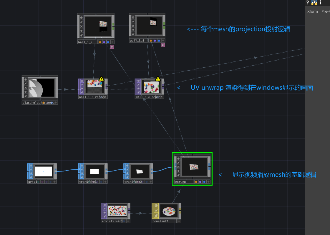
简单的TD mesh projection方案
A Simple TD Mesh Projection Workflow
不需要按照步骤操作,只是说明原理用途
This is not meant to be followed as strict step-by-step instructions. It is mainly to explain the principle and usage.
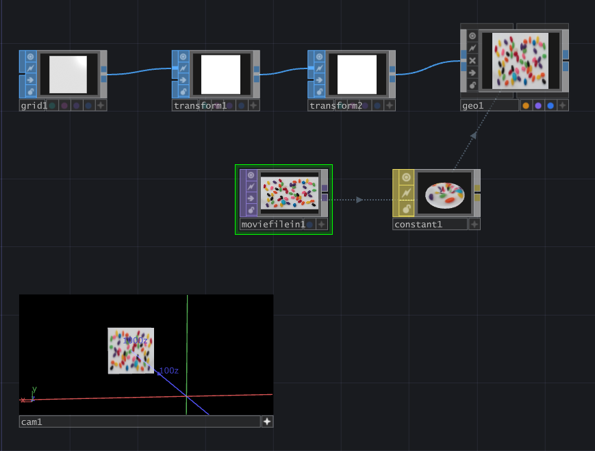
1 创建代表视频播放的3d卡片
1 Create a 3D Card That Represents the Video Playback
这里用两个transform的作用是,第一个transform控制mesh距离中心多远,下一个transform则是沿着中心旋转,类似于unreal ndisplay中,lightcard的逻辑,第一个transform是distance to center, 第二个是控制longitude 和 latitude。我在最终的项目中也是使用这两个节点来控制每个视频卡片显示的位置的。
Here, I use two Transform nodes. The first Transform controls how far the mesh is from the center, and the second Transform rotates it around the center. This is similar to the logic of light cards in Unreal Ndisplay. The first Transform is like distance to center, and the second one controls longitude and latitude. In my final project, I also used these two nodes to control the display position of each video card.
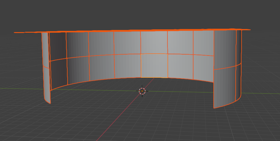
2 导入两个代表led屏幕节点的mesh
2 Import Two Meshes That Represent LED Screen Nodes
这里使用温哥华Node1 和 Node2 的mesh,也就是 Wall_1_2 和 Wall_3_4来展示,总之这里每个节点代表一个windows桌面。
Here, I use the Vancouver Node1 and Node2 meshes, which are Wall_1_2 and Wall_3_4, as the example. In general, each node here represents one Windows desktop.
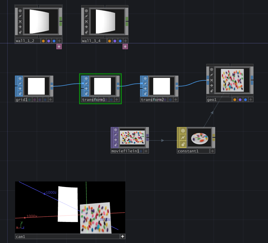
3 将代表视频播放的mesh,放置到合适的位置
3 Place the Video Playback Mesh in a Suitable Position
这里我把这个视频播放的mesh放在node1和node2的mesh后面,这里没什么特别的,只是说我想稍后能让node1和2有东西可以显示,并且验证画面是相连的。
Here, I placed the video playback mesh behind the meshes of Node1 and Node2. There is nothing special about this. I just wanted Node1 and Node2 to have something to display later, and I wanted to verify that the image connection between them works correctly.
4 进入对于每个led mesh的fbx节点,创建一个用于投射的camera,并且让camrea是看向这个led 屏幕mesh的
4 Go Into the FBX Node of Each LED Mesh, Create a Projection Camera, and Make the Camera Look at the LED Screen Mesh
这里的这个camera就相当于是,之前我们例子里提到的那个摄像机。而这个camera的位置就代表了default view point的位置。
This camera is equivalent to the camera we mentioned in the previous example. The position of this camera represents the position of the Default View Point.
这里你可能会有疑问,比如说相机的fov该设置为多少,因为毕竟fov的大小决定画面的大小。
At this point, you may have a question: what should the camera FOV be? After all, the FOV determines the size of the captured image.
在我最终的项目中,我有一个逻辑来根据每个mesh的四个顶点来计算其相机的fov,不过原则就是相机需要能够看到完整的mesh。
In my final project, I have a logic that calculates the camera FOV based on the four vertices of each mesh. But the basic principle is that the camera needs to be able to see the entire mesh.
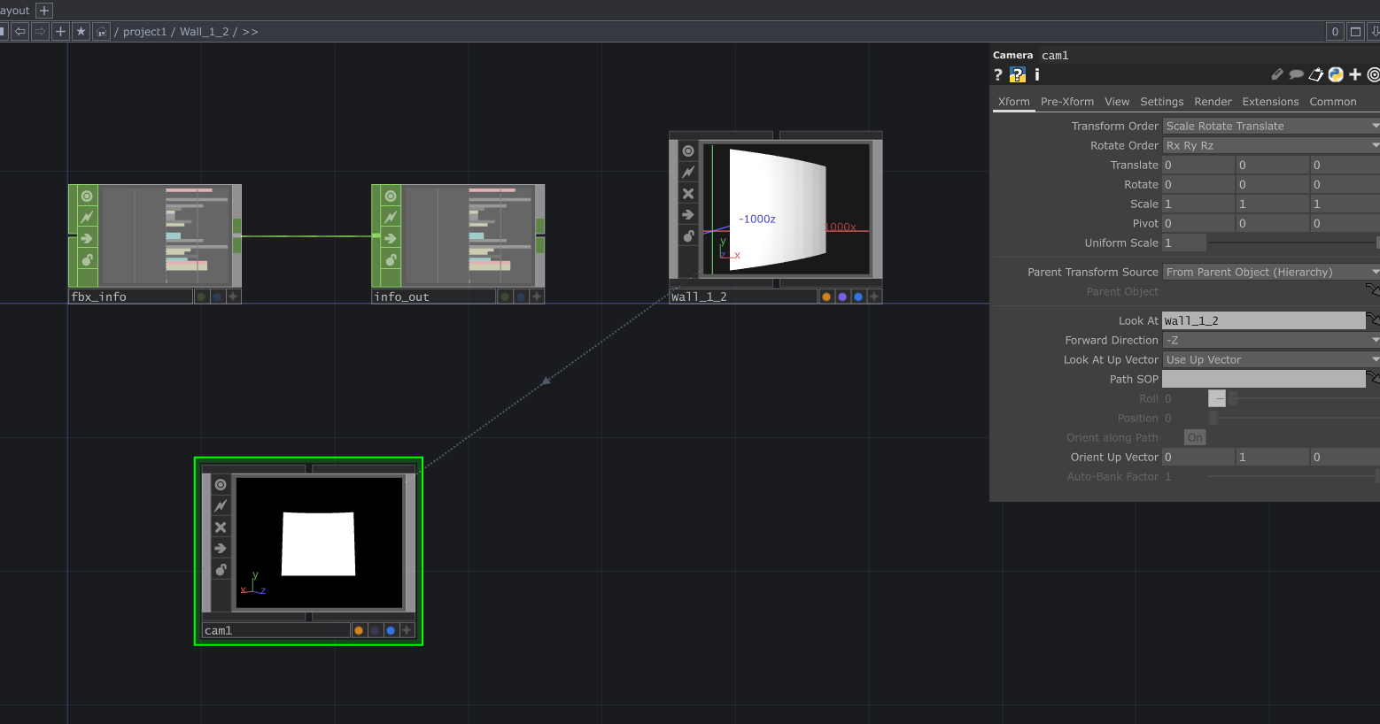
注意:为了能够在TouchDesigner中,使用相机look at功能,我们需要对LED的mesh进行处理。
Note: In order to use the camera Look At function in TouchDesigner, we need to process the LED mesh first.
默认的,工作流程制作出的用于unreal ndisplay的led mesh,每个mesh的中心点都是一样的,在坐标中心。这样当在TouchDesigner中,设置look at 到mesh的时候,其实是look at在(0,0,0)坐标。
By default, the LED meshes created for Unreal Ndisplay usually share the same center point, which is the world origin. So when we set Look At to the mesh in TouchDesigner, it is actually looking at the coordinate (0, 0, 0).
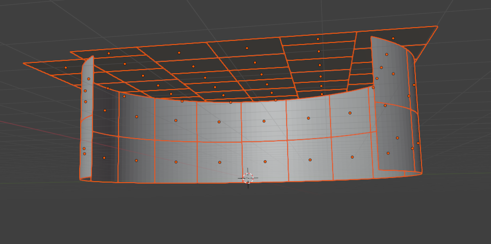
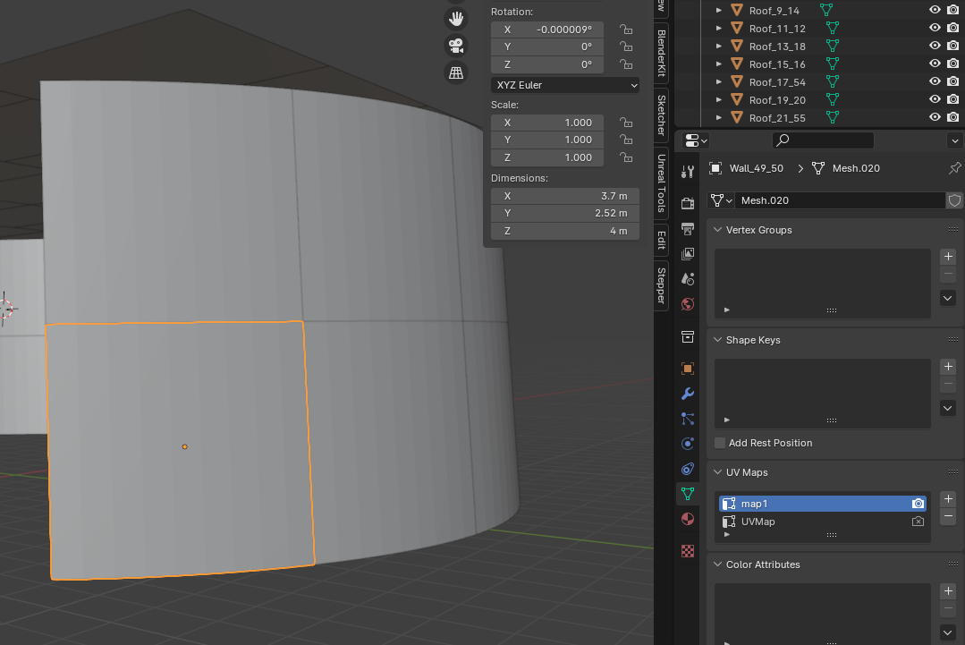
我们需要讲每个mesh的中心设置为其本身的中心,blender中可以通过设置 Origin to geometry 来实现。
We need to set the center of each mesh to its own geometry center. In Blender, this can be done by using Origin to Geometry.
这样TouchDesigner中,当Look At一个mesh的时候,才是看向这个mesh的位置。
In this way, when we use Look At on a mesh in TouchDesigner, the camera will actually look at the position of that mesh.
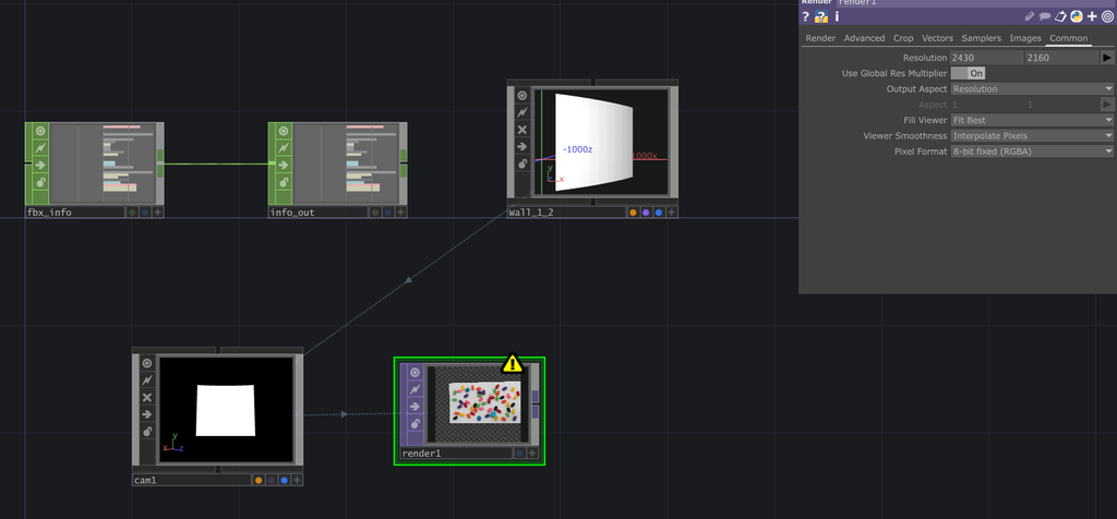
5 创建一个render,使用mesh的camera,渲染播放视频的3d mesh,这代表了前面我们例子中提到的,摄像机捕捉的真实世界的画面。
5 Create a Render Node, Use the Mesh Camera to Render the Video Playback 3D Mesh, Which Represents the Real-World Image Captured by the Camera in the Previous Example
注意我这里render的分辨率设置成为了,每个led屏幕的分辨率2430x2160,其实这是在开发早期,我对于这个部分的理解误区,后来我经过测试,其实任何分辨率和比例都可以,但是要记住这个比例因为后面会用于投射到mesh的步骤。比如你可以用1:1的比例,渲染2k的分辨率,都可以。
Note that I set the render resolution here to the resolution of each LED screen, which is 2430x2160. Actually, this was a misunderstanding I had in the early development stage. Later, after testing, I realized that almost any resolution and aspect ratio can work. However, you need to remember this aspect ratio because it will be used later when projecting onto the mesh. For example, you can use a 1:1 aspect ratio and render at 2K resolution.
其实严格来讲,应当更加精细的去计算这分辨率,因为此时相机拍摄到的画面,投射到led mesh上,肯定有损耗,因为可以看到周围黑色的部分,不在led mesh上的区域就被浪费掉了。我在最终项目中,通过计算每个相机的fov,来尽可能的找到一个小的fov来框住全部的mesh,所以损耗可以忽略。而且其次,播放视频和渲染Unreal场景不同,视频本身的分辨率就不大,那么落在每个led pannel上的部分就更加分辨率低了,所以其实也无所谓。
Strictly speaking, the resolution should be calculated more carefully. At this stage, the image captured by the camera will be projected onto the LED mesh, and there will definitely be some wasted pixels. As you can see, the black area around the mesh is not on the LED mesh, so those pixels are wasted. In my final project, I calculate the FOV for each camera and try to find the smallest FOV that can still frame the whole mesh, so the waste can be ignored. Also, compared with rendering an Unreal scene, playing back video is different. The video itself may not have a very high resolution, and the part that lands on each LED panel will be even lower in resolution, so this is not a big issue in this case.
这里你只要记住,确保这个相机拍摄到的画面够用,就可以了。什么是够用?
Here, you only need to remember that the camera image needs to be good enough. What does good enough mean?
1.画面范围包含led mesh
- The image range includes the LED mesh.
2.画面分辨率足够到你裁切和投射到led mesh所覆盖的区域
- The image resolution is high enough for the area that will be cropped and projected onto the LED mesh.
6 创建一个constant 材质,将这个render1的画面作为贴图,显示到led mesh上
6 Create a Constant Material, Use the Render1 Image as the Texture, and Display It on the LED Mesh
这里就是我们之前提到的,直接将相机画面,以贴图的形式给到led mesh,肯定是不对的。
This is what we mentioned before: directly applying the camera image as a texture to the LED mesh is definitely not correct.

7 改变贴图的应用方式,变为从相机投射贴图
7 Change the Texture Application Method to Projection From Camera
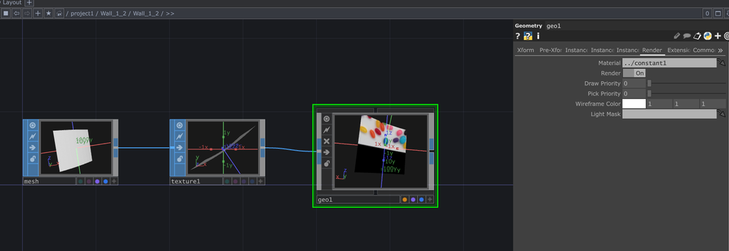
这里进入Wall_1_2的geometry节点,本身这里面只有一个 mesh节点,我们添加一个texture 和 geo节点,在texture节点里,选择texture type为 perspective from camera, 并且设置camera name 为 ../cam1,也就是刚才放置在Wall_1_2 fbx节点中的那个投射相机。
Here, go into the Geometry node of Wall_1_2. Originally, there is only one Mesh node inside. We add a Texture node and a Geo node. In the Texture node, set the Texture Type to Perspective from Camera, and set the camera name to ../cam1, which is the projection camera we placed inside the Wall_1_2 FBX node.
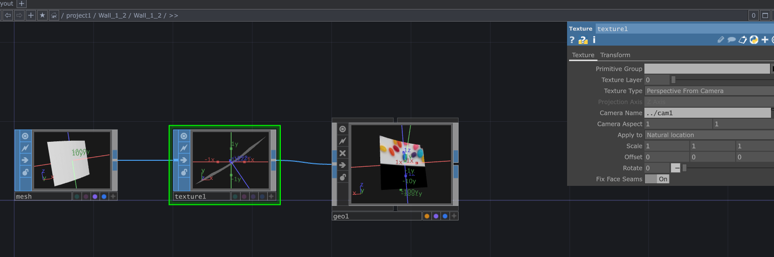
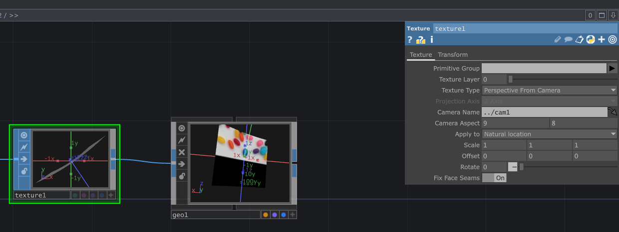
注意,此时texture节点中,还需要设置camera aspect要完全符合之前我们提到的那个投射相机画面比例,需要和那个一样。例如我的流程就是设置成了led屏幕的分辨率比例,前面投射相机的画面比例为2430x2160,所以这里我也设置成了9:8。但如果你那里用了1:1的2k分辨率,这里就保持为1:1比例。
Note that in the Texture node, the Camera Aspect also needs to exactly match the aspect ratio of the projection camera image we mentioned earlier. For example, in my workflow, I used the aspect ratio of the LED screen resolution. The projection camera image ratio was 2430x2160, so I set this to 9:8. But if you used a 1:1 2K resolution, then you should keep it as 1:1 here.
同时记得设置geo1的材质为刚才我们创建的材质。
Also remember to set the material of geo1 to the material we just created.
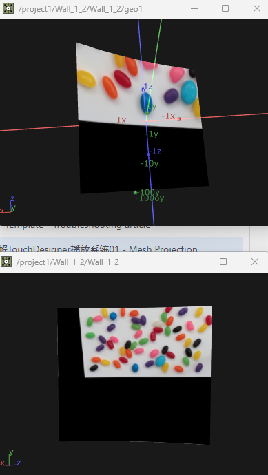
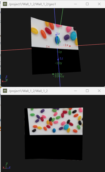
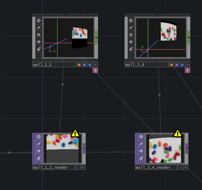
此时我们能看出来,这两种贴图应用的方式的区别了。从下图看出,上面的画面代表是,投射在mesh上的,正确的画面,而下面代表是相机原本拍摄到的画面。也就是我们从相机拍摄的画面中,只选择led mesh范围内的内容,然后展示在led mesh上。
At this point, we can see the difference between these two texture application methods. In the image below, the top image represents the correct image projected onto the mesh, while the bottom image represents the original image captured by the camera. In other words, from the camera image, we only select the content inside the LED mesh area and display that content on the LED mesh.
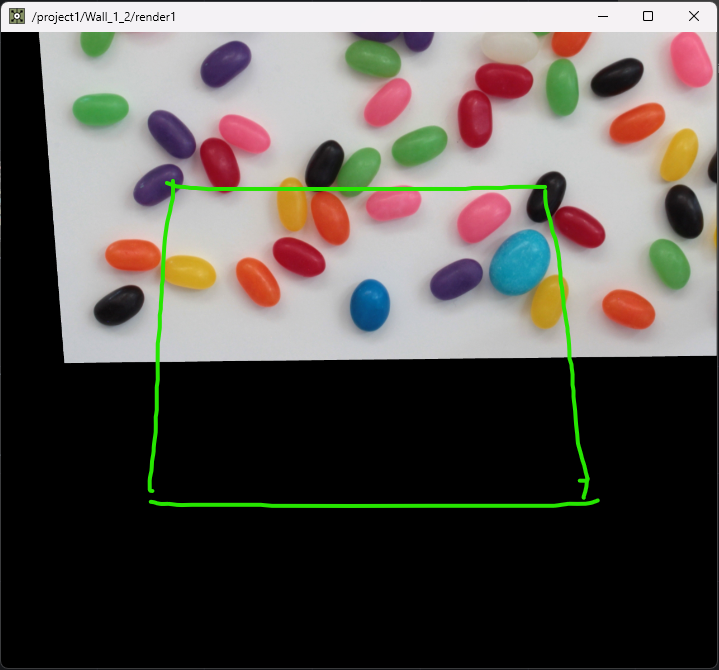
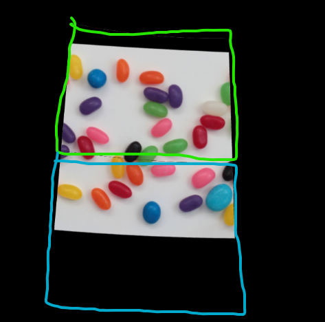
可以这样理解,如下图,这时相机拍摄到的画面,而图中绿色代表的是led mesh的位置和范围,我们其实只需要绿色框框中的内容,将其投射在led mesh上。
You can understand it like this: in the image below, this is the image captured by the camera, and the green area represents the position and range of the LED mesh. We only need the content inside the green frame and then project it onto the LED mesh.
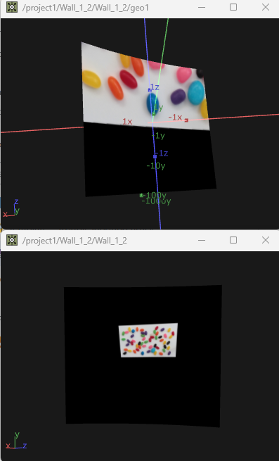
为了验证我们的理论是对的,这时候,我无论如何改变相机的fov,虽然相机拍摄的画面会变,但是投射在mesh上的部分永远是一样的。当然你要确保fov的数值能够使得相机的视窗包含整个led mesh,否则led mesh范围内的画面都没拍到,投射的时候就没有这个信息了。
To verify that our theory is correct, I can change the camera FOV in any way. Although the image captured by the camera changes, the part projected onto the mesh always stays the same. Of course, you need to make sure the FOV is large enough for the camera view to include the entire LED mesh. Otherwise, if the image inside the LED mesh area was never captured, there will be no information to project.
8 创建用于输出用于windows显示的画面
8 Create the Output Image for Windows Display
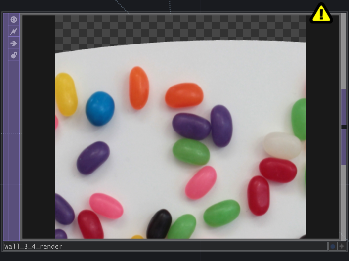
这时候,其实我们所需要的信息已经得到了,也就是上一步图中的上半部分的画面。我们需要得到那个画面以led mesh uv展开的一个结果,从而给windows显示。
At this point, we already have the information we need, which is the top part of the image from the previous step. Now we need to get the UV unwrapped result of that image on the LED mesh, so it can be displayed by Windows.
这时,创建一个renderer,将其render mode设置为 UV Unwrap模式。
Now create a Renderer and set its Render Mode to UV Unwrap.
Geometry我使用的是,Wall_1_2中我们刚才自己创建的一个新的geo1节点,这个节点连接这我们创建的texture节点,也就是使用的从camera 投射的方式应用贴图。此时我们能看到,这个Wall_1_2_render画面得到的就是前面我们看到的,投在led mesh上的画面以UV展开的结果。
For Geometry, I use the new geo1 node we just created inside Wall_1_2. This node is connected to the Texture node we created, which means it uses the texture projection from camera method. At this point, we can see that the Wall_1_2_render image is the UV unwrapped result of the image projected onto the LED mesh.
Camera我使用的是一个,随便的camera,这个camera无所谓的因为uv unwrap的渲染方式不需要相机,但是TouchDesigner的render节点必须要一个camera才能工作,所以起到占位的作用。
For Camera, I use a random camera. This camera does not really matter because UV Unwrap rendering does not need a camera. However, TouchDesigner’s Render node requires a camera to work, so it is only used as a placeholder.
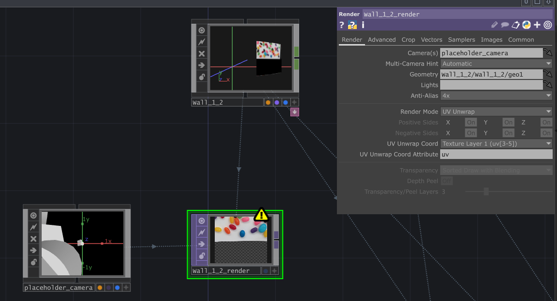
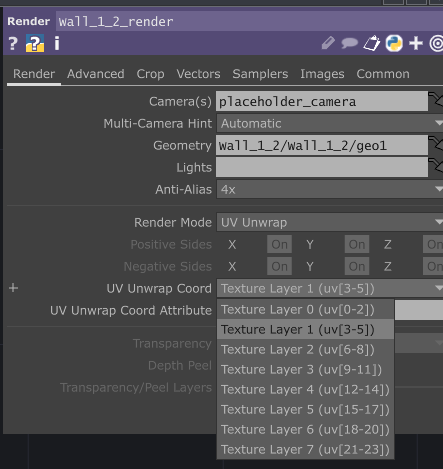
注意,这个render的uv unwrap coord 要选择 Texture Layer 1 (uv[3-5]),而不是默认的Texture Layer 0 。也就是说,要使用mesh里的第二个UV map进行unwrap的方式渲染。所以其实前面提到的LED mesh处理,除了设置中心到mesh本身,还有一步,是要复制一个uv map,也就是每个mesh需要有两个相同的uv。 这里我的理解是,在TouchDesigner中,每个mesh的第一个uv用于前面我们提到的,从相机投射贴图,可能已经被占用了或者被改写了。所以需要用第二个uv来进行uv unwrap的渲染。
Note that the UV Unwrap Coord of this Render needs to be set to Texture Layer 1 (uv[3-5]), instead of the default Texture Layer 0. This means we need to use the second UV map inside the mesh for the unwrap render. So for the LED mesh processing mentioned earlier, besides setting the center to the mesh itself, there is another step: copy the UV map. Each mesh needs to have two identical UV maps. My understanding is that in TouchDesigner, the first UV of each mesh is used for the camera projection texture we mentioned earlier, and it may already be occupied or modified. So we need to use the second UV for the UV unwrap render.
在Blender中,只要复制一份同样的uv map就行,确保每个mesh有两个uv就好。
In Blender, you only need to duplicate the same UV map. Just make sure each mesh has two UV maps.
9 测试搭建完成,验证结果
9 Finish the Test Setup and Verify the Result
此时,我们将得到两个画面:
At this point, we will get two images:
其实,仔细看可以看到我们前面讨论的,有关于画面反扭曲,和扭曲的过程:
Actually, if we look carefully, we can see the reverse distortion and distortion process that we discussed earlier.
比如,对于Wall_3_4这个led mesh来说,视频播放的那个mesh是个矩形,是没有弧度的,而通过我们刚才那么一顿操作,这个视频播放的mesh的边缘,竟然变弯曲了。这是因为每个节点的led屏幕,是自带弧度的,向内凹进去的。
For example, for the Wall_3_4 LED mesh, the video playback mesh is a rectangle and does not have any curvature. But after the operations above, the edge of the video playback mesh becomes curved. This is because the LED screen of each node has its own curvature and curves inward.
所以可以先想象一下,如果把这个画面,显示在一个,向内凹进去的led 屏幕上,那么看过去,这个视频的上边就被扭曲回平的了。这也间接证明了,我们这套方法的正确性。
So we can imagine that if this image is displayed on an inward-curved LED screen, the top edge of the video will be distorted back to a straight line when viewed from the correct position. This also indirectly proves that this method is correct.
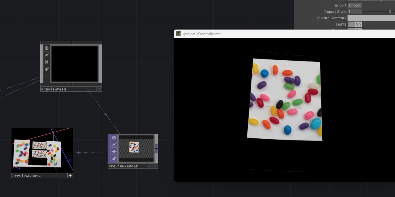
接下来,我搭建了一个测试用的,用于预览的节点组。其实就是把得到的画面贴图,应用在led mesh上,然后渲染出来。可以看到画面完美拼接起来了。并且我大概讲预览相机放置到和投射相机相同的位置,也可以看到,刚才我们提到的那个视频上边缘的弧度,会在最终大屏幕上变平的现象。
Next, I built a test node group for previewing the result. It simply applies the generated image texture back onto the LED mesh and renders it out. We can see that the images connect perfectly. I also roughly placed the preview camera at the same position as the projection camera, and we can see that the curved top edge of the video mentioned earlier becomes flat on the final large screen.
结论
Conclusion
至此,我们得到了一个简单的,具有Ndisplay那样的投射方式的,TouchDesigner视频播放系统。
At this point, we have created a simple TouchDesigner video playback system that uses an Ndisplay-like projection method.
其核心就是,有关投射和uv unwrap渲染的部分。
The core part of this system is the projection and UV unwrap rendering workflow.
而这部分为什么这么重要呢?其实也就是和为什么Ndisplay显示重要的答案一样。
Why is this part so important? The answer is basically the same as why Ndisplay rendering is important.
我们能够在LED屏幕上,得到,从相机视角的正确透视的画面。通常在温哥华,拍摄车戏的时候,我们会讲default view point,设置到当前摄影机的位置(使用stype追踪),从而得到正确的透视。
We can get the correct perspective image from the camera’s point of view on the LED screen. Usually in Vancouver, when shooting car scenes, we set the Default View Point to the current camera position, using Stype tracking, so we can get the correct perspective.
我们能够跨越墙屏和顶屏的显示一个整体的画面,这和Unreal的ndisplay逻辑是一样的。
We can display one continuous image across the wall screen and ceiling screen. This is the same logic as Unreal Ndisplay.
如果理解了这部分的逻辑,那么其他在我完整的项目中的功能,相比而言,更加直观和易于理解。例如,lightCard 功能,调色功能,视频文件索引功能,视频同步播放功能,控制参数保存管理功能等等。
Once this logic is understood, the other features in my complete project become much more intuitive and easier to understand. For example, the LightCard feature, color adjustment feature, video file indexing feature, synchronized video playback feature, control parameter saving and management feature, and so on.